Modifying a 1952 Chevy Truck. Original bodywork - modern upgrades.
www.1952ChevyTruck.com
www.1952ChevyTruck.com
March 2016 - April 2016. Upgrading the original gauge cluster to
modern electrical gauges but still look original.
Modifying the 4 gauges so that modern electrical sensors can be used and a safer voltmeter for battery
charge monitoring (without affecting appearance / still looks original).
The problem with the gauges is they use 1947-53 technology and this has many disadvantages.
1. The oil pressure gauge.
A narrow pipe goes from the engine to the gauge and the pipe contains oil at high pressure. The correct name
for the gauge (in Physics) is a Bourdon Gauge. This is a flat pipe in a curved shape. When the oil pressure
increases (e.g. truck is started) the curved flat pipe tries to straighten out. A blow type "party trick" is
actually a paper Bourdon Gauge. When blown into it straightens out (due to increased pressure) and makes a noise.
The problem with this type of gauge is the issue of the pipe leaking usually at a joint and oil leaking into the
cab and onto the carpet at high pressure. This also makes the vehicle unusable as oil from the engine is being
lost and oil pressure is falling. Leaks at the junctions is usually due to a failed "olive" (ferrule). Modern
gauges are electrical using an electrical sensor in the engine and wires to a moving coil (or digital) meter.
2. The battery charge indicator gauge.
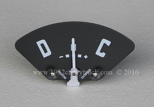
This is an ammeter. The current from the battery to the fuse box (which carries all of the current except the
current going to the starter) must go through the ammeter. This means the wires going to and from the ammeter
are carrying a massive current of over 30A. Any kind of short circuit and the wires will burn and melt. Using
an ammeter for monitoring battery charging is a fire risk. The modern method is to monitor the charging and
discharging voltage not the current. Only a very small current goes through a voltmeter. A voltmeter is a
moving coil, moving magnet (or digital) meter.
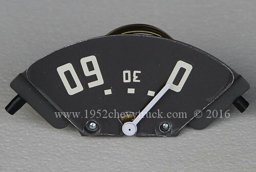
3. The fuel gauge.
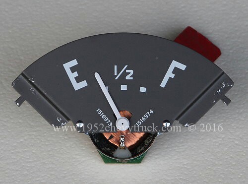
The original 1952 meter is a moving magnet meter. A magnet is connected to a pointer and held between two coils,
the sender unit in the fuel tank consists of a float connected to a variable resistor, the variable resistor is
connected across one of the coils on the fuel tank gauge. The sender unit must have the correct value of
resistance to suit the fuel gauge. The original moving magnet meter needs a sender unit with a variable resistance
of 0 - 30 ohms. When the tank is empty the resistor reads 0 ohms and when it is full the resistors reads 30 ohms.
A modern fuel gauge uses a moving coil meter. (The coil is within a magnetic field). Here a typical sender unit
has a variable resistors with a value of 240 ohms when the tank is empty and 33 ohms when the tank is full.
The water / oil temperature gauge.
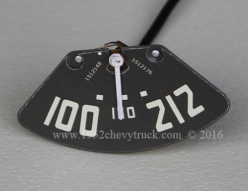
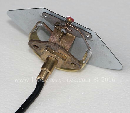
The original mechanical temperature gauge used an inflexible thin copper capillary between the engine and the gauge.
This is also a Bordon Gauge. The coolant heats up the alcohol in the gauge and it unwinds moving the pointer. A modern
gauge is a moving coil (or digital) meter. The sensor is a modern electrical sensor and the sensor is connected
to the gauge by wires. The gauge is sensing changes in voltage and is calibrated in degrees.
From all of this background information it is clear that modern gauges can all be moving coil or moving magnet meters
with electrical wires connecting to the engine sensors, fuel tank sender or to the battery. All of the currents going
through the meters are low as the meters are actually voltmeters but calibrated to the 4 types of monitoring
parameter required.
Moving magnet meters. What to buy.
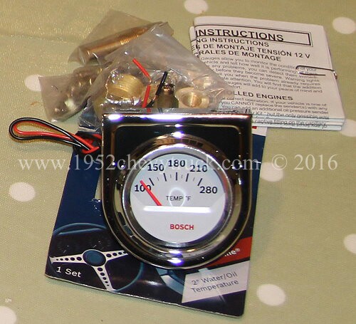
Modern moving magnet meters are quite cheap. Typically they are about $20 each (x4) and about $15 for a matching
tank sender unit. The other gauges come with the appropriate sensor where applicable. This means all 4 of the
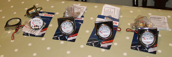
gauges and sensors are less than $100. They are - Bosch Performance (formerly Sunpro) gauges 8201, 8202, 8205
and 8209 and are all available from Summit Racing. The problem is - They are all separate and do not look
original like the original cluster which holds the 4 original gauges. It is possible to buy a cluster of 4
moving coil meters and the cluster exactly fits the hole in the truck, however, all of these after-market
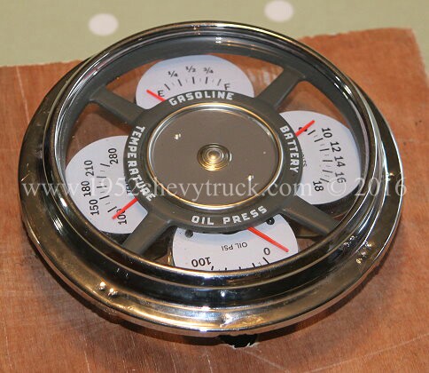
clusters for the truck look after-market. None of them look like the original cluster. Clearly this is a
matter of opinion but I don't think anything looks as good as the original cluster. The whole point of this
project is to make a cluster which looks original but uses modern metering.
The ideal fuel sender unit for this type of fuel gauge is detailed towards the bottom on this page.
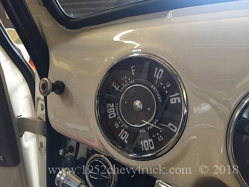
Aims.
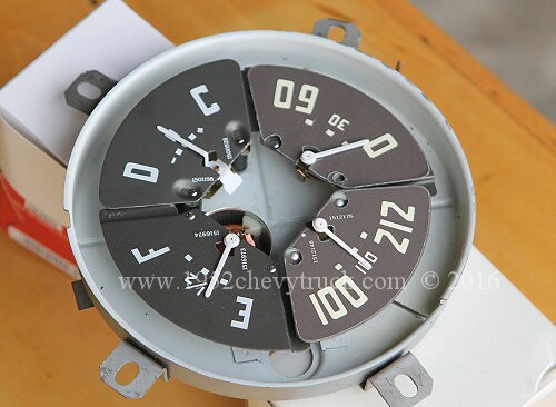
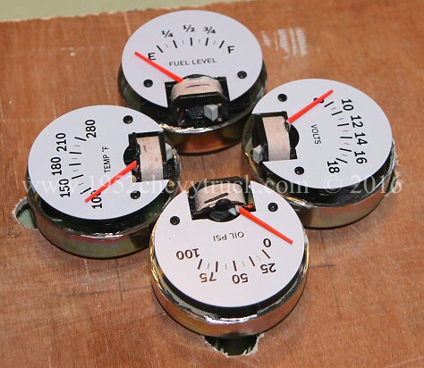
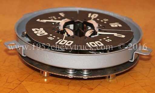
The purpose of this project is to see if the 4 separate moving magnet meter gauges can be stripped out of their
enclosures and fitted into the original cluster. They will also need to look original with brown displays and
white/cream calibrations. A good start is that all 4 gauges listed above have a scale which has a small
curvature and of a similar curvature and length of curvature as the original gauges.
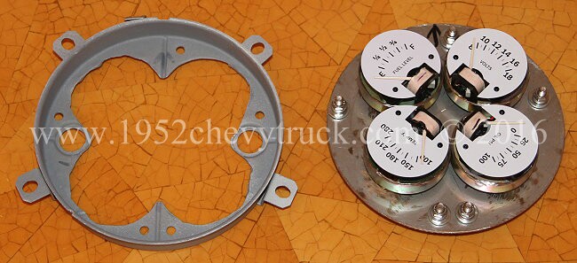
Converting the cluster.
Note a useful starting point - The voltmeter for measuring battery charge status. "Swapping your ammeter for a voltmeter"
There is some very good useful information by "Mike" at www.stovebolt.com modifications
We are not doing it exactly the same way and we are converting 4 gauges not 1, but it is very worthwhile reading Mike's notes.
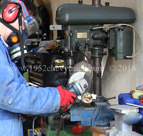
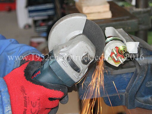
All of the gauges needed cutting open using a mini grinder and 1mm cutting disk. Safety equipment must be worn.
Before cutting open the gauges, please read the update below for a better procedure for cutting the gauges.
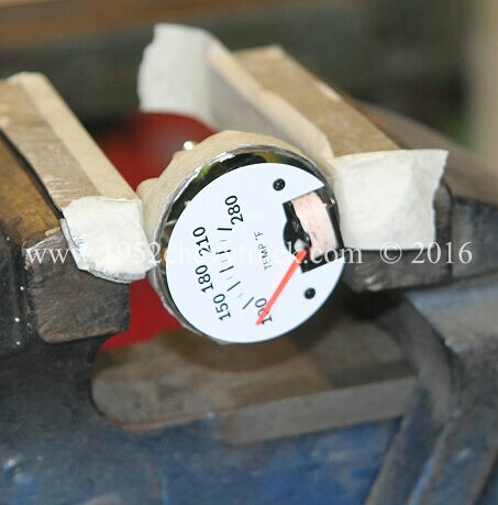
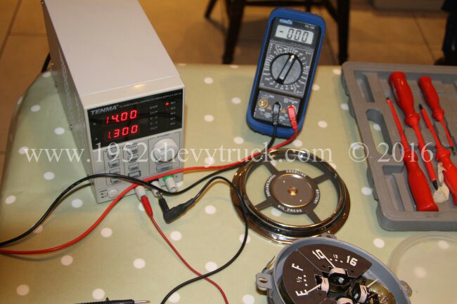
At this point it is important to note that the gauges need to be checked. To check the gauges apply a voltage. Use
a bench power supply or a 12 volt battery. I used a 0-30v variable bench power supply. These are available for about
�40.00 ($60.00). I set it on 12V and 14V. e.g. the fuel gauge reads 3/4 on 12v and full on 14v.
There are 2 reasons why the gauges might not work-
1. There could be raggy edges on the metal (swarf) needing to be removed. Check the pointers move freely by moving
them with a finger. Remove the circular white calibrated display plate by carefully removing the two small bolts.
Cut raggy edges off near the bottom end of the pointer if required with a modelling knife.
2. It is likely iron filings will have got onto the magnets from the cutting disc. In our gauges, three of them did
not work properly. Removing the iron filings needs either good eyesight or a magnifying glass, a thin screwdriver
with a piece of thin double sided adhesive tape on the end forming a narrow tongue and about 1 hour (at least) of
painstaking removal. The reason for double sided tape is not because it needs to be double sided. This type of
tape has a rigid backing and so the tongue is not too floppy and can be applied to the filings on the magnets.
Keep changing the tape as more and more filings are removed. Especially also at the bottom of the magnet where
there is a narrow gap to slide the tape into. (Note- the magnets are inside the coils)
After cleaning / removing the filings, one gauges did not work perfectly. See update below.
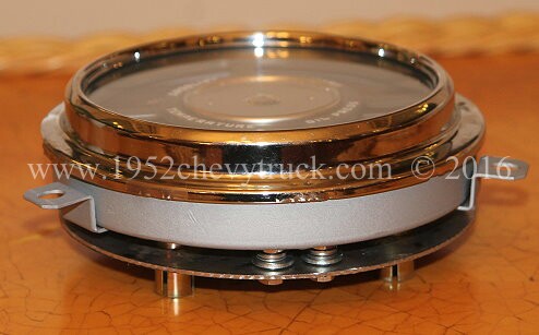
The gauges were test fitted onto thin ply wood to test the spacing.
Laying the original gauge glass face on top of the gauge cluster checks the spacing.
A piece of stainless steel plate was sourced from a local fabrication company. They also cut it to the required diameter.
It has a protective film on the back. This was not removed. It is ideal for marking out using a pen or pencil and even
when finished it does not need to be removed.
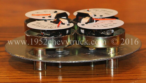
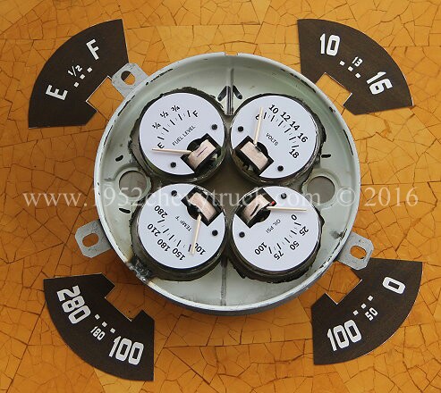
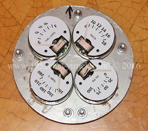
The gauges were mounted onto the stainless steel circular plate.
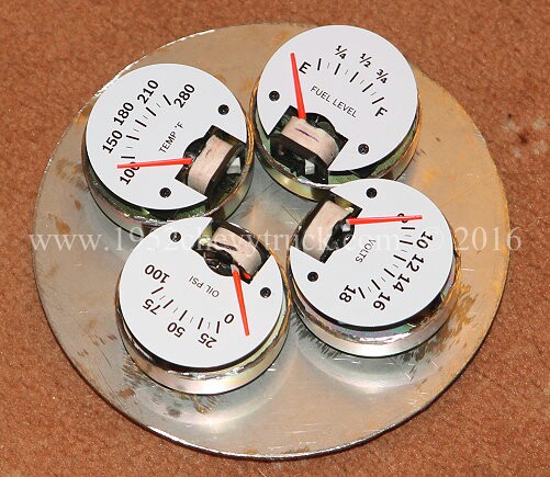
Laying the gauge face on top of the gauge cluster checks the spacing.
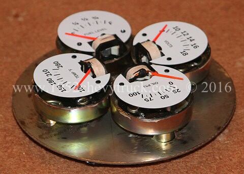
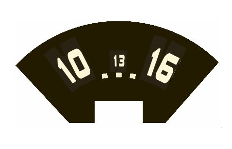
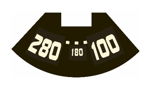
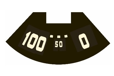
Making the new (original appearance) decals.
Once again my compliments to Mike at www.stovebolt.com for his advice on this subject. I used a different method
but was able to use one of his templates to help me. The program I am most familiar with and have used for many
years is Serif Page Plus (version X7 at the moment). This is a very inexpensive program and works extremely well.
I used it to produce the new lettering. I downloaded the voltmeter jpeg from the �stovebolt page� and inserted it
into Serif. This gave me two very important starting points. Since the import was actual size, it gave me the size
of the lettering. Secondly it gave me a guide to match the background colour and the colour of the lettering. I
decided I preferred the light cream lettering to the off white lettering. I could not find a font which was exactly
the same but I did find a font which was close. Using the decal from Mikes page I inserted new lettering.
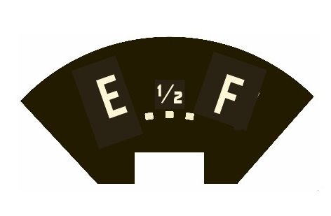
It is important to make 2 decals before using Serif, Simply invert the decal and save it to a new file as two
of the decals need to be the other way round for the oil pressure and the water temperature. Within the Serif
program it is possible to set the background colour and the letter colour. I found the best match for the
background was Red 42, Green 34 and Blue 18. The best match for the light cream lettering was - Red 255,
green 245 and blue 215. The font I used for the numbers was - "BoltsSF" and for the letters (E and F)
for the fuel gauge - "Franklin Gothic Medium Cond" The large lettering size was 50 and the small lettering
size was 20. The width was set at 50% for the most of the letters and 70% for the "1/2" on the fuel gauge.
All of this information may be useful for anyone using a different program but you can download the actual
Serif files below if you intend to use that program. This would be the easiest option as the work has been
done for you. However, it only took me about 3 hours to do this work and anyone good at IT and used to this
type of process could use a different program. I purchased Serif Page Plus X7 from Amazon for �30.00 ($42.00)
I recently also used it to draw the plans for the extension on my daughters house and countless other uses. If
you not familiar with this program, it does not matter as all you have to do is download the 4 files below,
open them in the program and print them. They will automatically print the correct size. jpgs are also
available below but they might not print the correct size and may need adjusting.
The "Serif" file - All Decals. The jpg file - All Decals
The circular white calibration plates were put onto the new (old style) decals and using a small drill just
held in the fingers, the holes through the card were drilled. The decals were then mounted onto the gauges
using the small bolts. Tighten very carefully by feeling for when the bolt is fully in but not compressing
the card. It is possible (according to Mike) to strip the threads but this did not happen here.
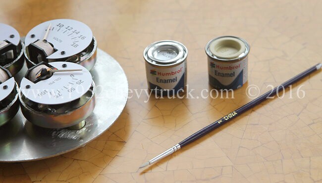
A tin of white and a tin of cream �Humbrol� modelling paint and a thin brush was purchased from a local modelling
shop. About 6 parts white to one part cream was used and the red pointers were painted. The red still showed
through and a second coat was needed.
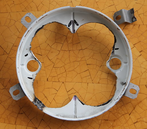
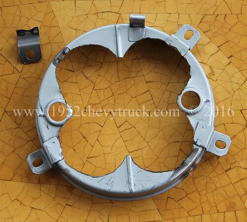
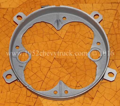
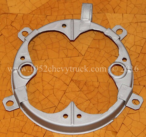
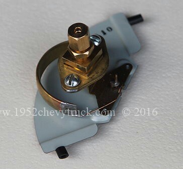
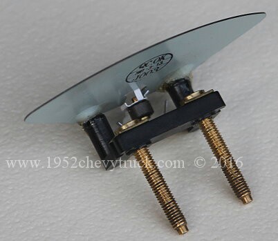
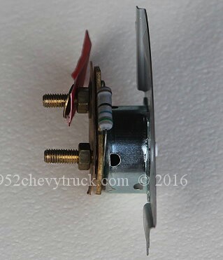
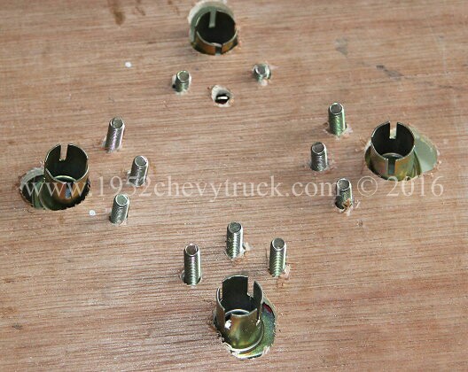
The original gauge back was cut. The pictures show the rough cut and then below the cleaned up cuts and some
paint applied. A mini grinder with 1mm cutting disc did most of the work. The cutting disc was later replaced
with a grinding disc to finish off. A smaller diameter worn grinding disc worked best. During this process one
of the lugs which holds the gauge on the inside of the dash dropped off. Our local fabrication shop welded it
back on with a small torch, gas welding appliance. I am very lucky ... my business buys many items every month
from them and so "truck jobs" are free!
It is important to get the spacing right between the new back plate and the old one so that the glass face sits
on the top correctly. I found one nut, four thin washers and one thick washer provided the 8mm which worked well.
Since photocopying thick gauge paper (card) was used. The decals had enough rigidity to be self supporting.
The paper (card) was from one of the "Jessop" stores. Printing using a normal budget printer worked fine.
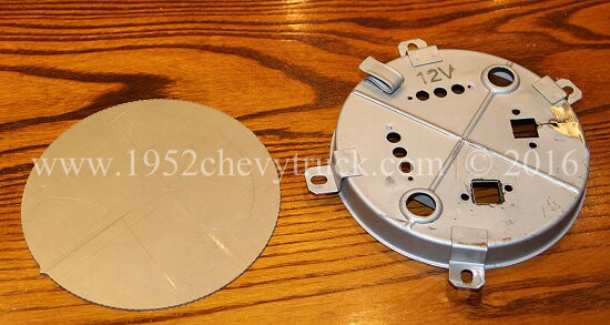
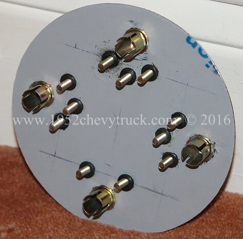
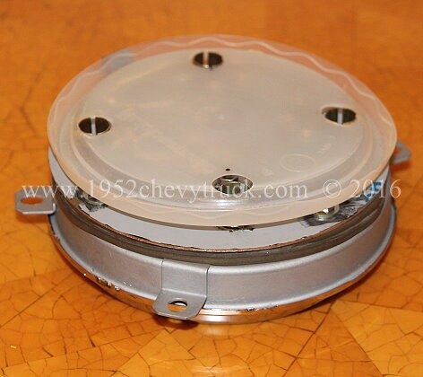
A plastic ice cream carton top provided the insulation on the back. This will be held in place by the illumination bulb holders.
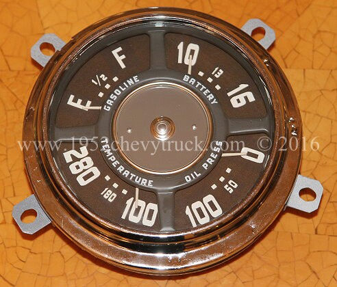
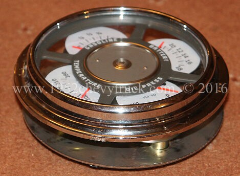
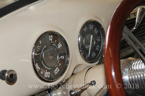
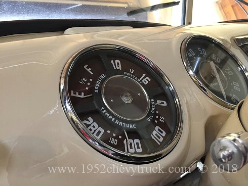
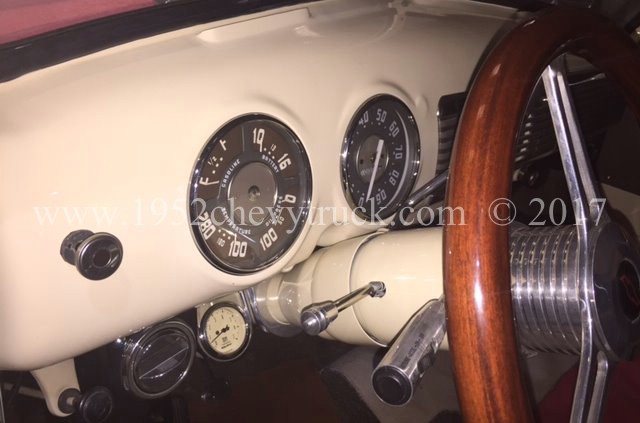
It is now possible to see how close this modern set of gauges looks compared to an original cluster from 1947-53
In my opinion it looks much better than the after-market modern gauges now available which look nothing like an
original gauge. Time? I started a couple of weeks before a 4 week business trip and finished a couple of weeks
after I got back. If I had to add all of the hours together, it would probably have been about a weeks work.
However, now that you can see how it is done (I had to design and solve problems) it should take less than that.
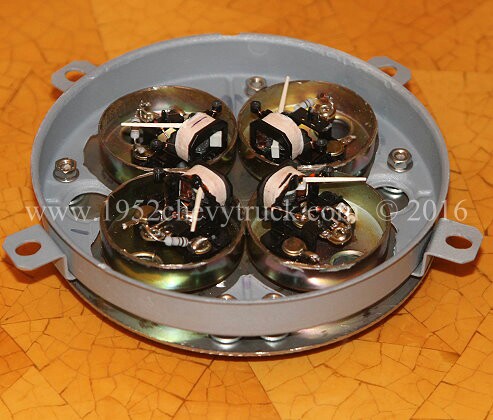
Update 31st May 2016 - Illumination problems.
Putting bulbs into the 4 holders in the backs of the 4 gauges produces poor results with both hotspots and
an uneven spread of light. A test with a bulb right in the centre produced perfect results. The gauge cluster
now needs a strip down so that a hole can be made in the centre for one bulb. See the next update below.
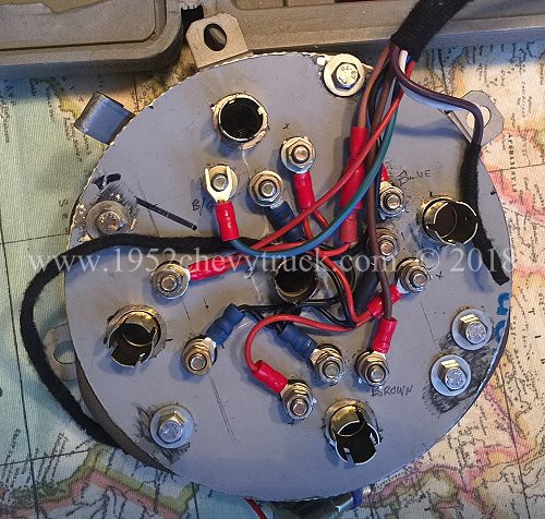
Update 31st May 2017 - Illumination problems solved.
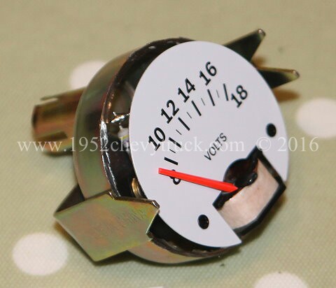
Check out the picture above of the back of the gauge which also shows the wiring connections. There are 5 places a
pea bulb can be pushed in, it can go in each of the meters, or you can see I put an extra one in the centre.
If you put bulbs into the 4 meter holes the light is too bright and not diffused enough. It is best to fit a
socket right in the centre. Epoxy Resin was used to fit this extra socket. Looking at the plastic back cover
above, an extra hole is needed in the centre for the single pea bulb. When this was tested it was the opposite
problem, not quite enough light to spread through the whole cluster. The solution (update February 2018) was
to coat some surfaces inside the gauge with aluminium foil / kitchen roll. It was stuck on with the same spray glue
used to stick the fabric and foam to make the door panels. It was stuck around the inside perimeter of the whole
4 gauge cluster casing, under the pea bulb, on the inside of the glass front in the centre and on the edges of
the individual gauge casings which border the pea bulb. All of this reflective foil then allowed the pea bulb
to provide the ideal amount of diffused light for the whole cluster. Pea bulbs did come with the meters but they
are filament and white. After a bit of research, 12V blue LED SG9 bayonet fitting pea bulbs were found at
www.rapidelectronics.co.uk at �1.19 each (they are also available from Amazon). The extra push-in pea bulb
fittings (with cables cut off and no bulbs inside them), can be pushed into the other holes as this all
helps to hold the plastic cover (which forms an insulated back) onto the back of the gauge cluster
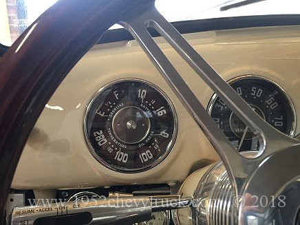
Update March 2017 You can see in the pictures below, there are extra gauges hanging below the dash.
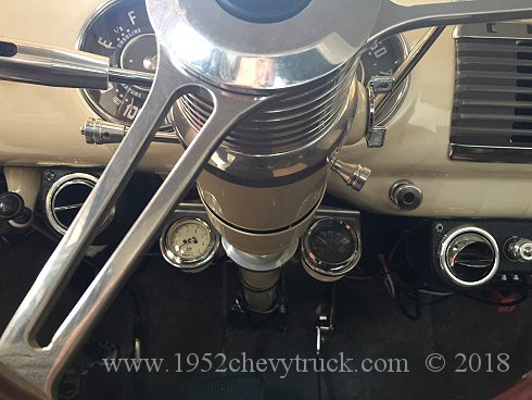
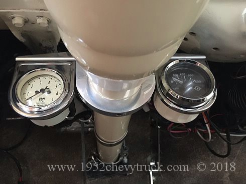
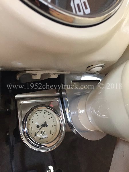
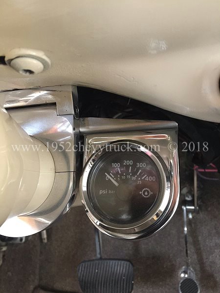
The chrome surrounds which come with the Bosch gauges are ideal for hanging extra gauges. Using a custom made
bracket across the top of the column there are 2 extra gauges, symmetrically placed each side of the column
under that dash. The one on the left is a rev counter and the one on the right monitors the oil pressure in
the automatic transmission. This needs a 0-400psi gauge made by "VDO" A VDO 0-400psi sender has to be
screwed into the side of the transmission and wired to the gauge Unfortunately VDO (the only company
who makes these meters) do not do a meter which looks as good as the meter on the left (would have
been better if they had matched) but anyway the 2 meters still look fine.
Update August 2017 How to avoid iron filings from getting into the meter movements.
Following the procedure above to cut open the gauges, there is a danger that iron filings will get
into the meter movements. Whilst it is possible to remove these using the method listed above,
this may not be 100% successful. With this cluster there was a problem with the fuel gauge reading
low even though the attempts to remove all filings seemed to work. It had to be replaced and so
a better method was found to cut the casing with the movement already removed.
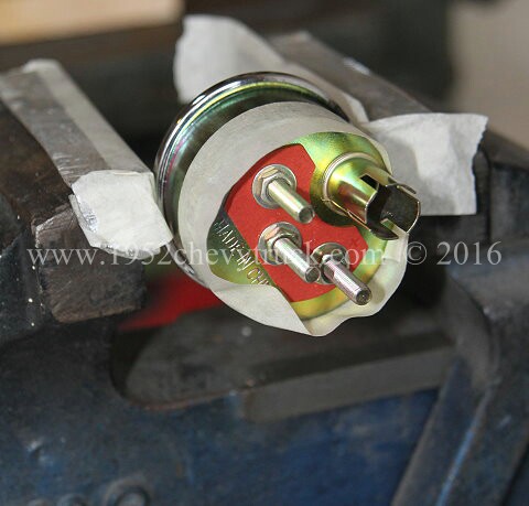
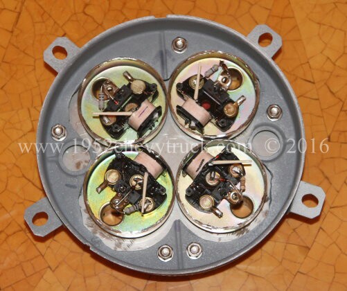
The solution was to remove the internal meter movements before cutting the casings with a mini grinder
and cutting disc. This can be done by prising the front of the gauge off with some pliers. Round
nose pliers worked well. Removing nuts on the back and the internal movement can be slid
forward and completely removed. The casing can then be cut. Clean up and refit the
movement. See pictures above of the casing with front prised off.
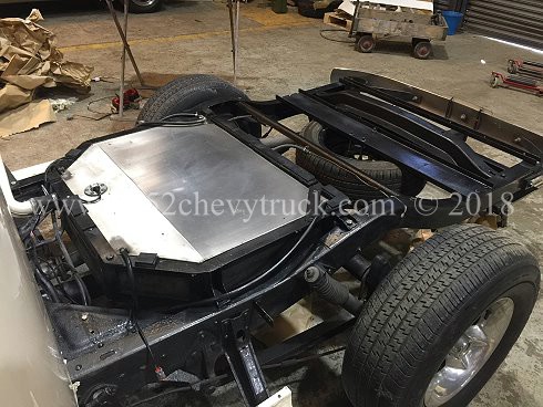
Update March 2017. Fuel tank gauge accuracy upgrade.
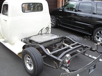
The bed was removed from the truck so that some update work could be done to the fuel tank and fuel sender unit.
(See the original notes, designs and building of the fuel tank in 2008)
Tank system mods -
This mainly related to installing a more accurate fuel gauge sender unit, however, some extra
work was done on the filler tube and the venting pipes. It is very important all venting pipes
are terminated into the filler tube so that if any fuel comes out of them it can't spill. Secondly
there was an obstruction in the filler pipe designed to insure the correct fuel nozzle went in but
this was causing problems. Removing it enables the fill rate (flow rate) to increase.
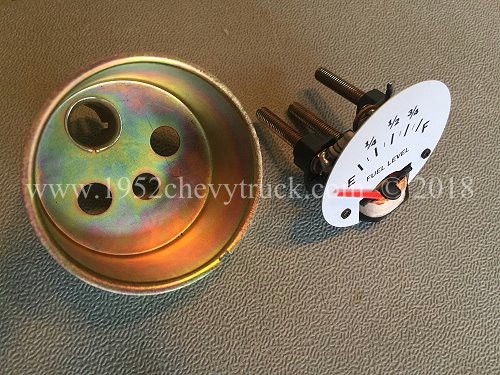
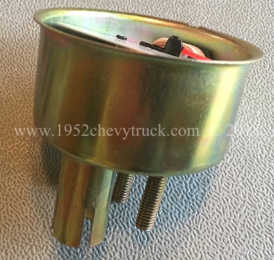
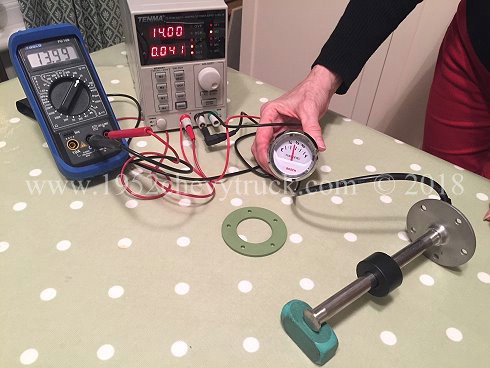
Fuel sender unit -
The fuel senders in most fuel tanks are pretty crude. They involve a float and variable resistor
inside the fuel. A better system uses reed switches and the detection system is not in the fuel.
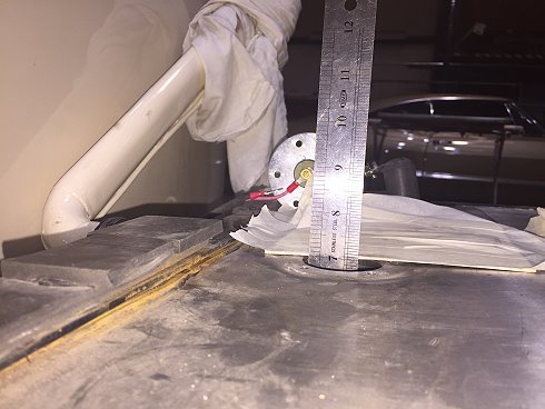
The picture above right shows the old variable resistor type sender removed and a steel ruler dipping the
tank for depth. The reed type senders come in various lengths and the depth of the tank needs to be known.
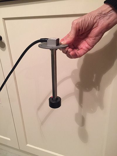
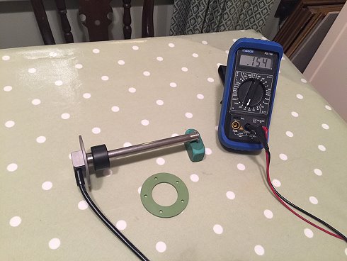
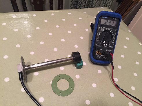
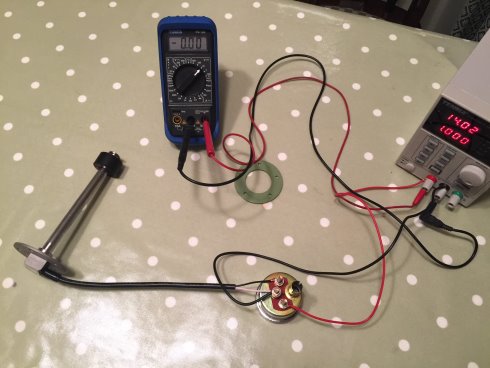
The two pictures below show the reed sender unit. The float is in two positions. The reed sensors which do
the sensing are inside the sealed aluminium tube and not in the fuel. This makes for improved reliability.
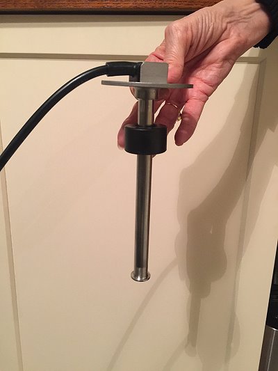
The 2 pictures below show resistance measurements being taken. Float high reads 0.156 ohms (almost zero).
Float low (empty fuel tank) reads 241 ohms. This is exactly correct for the type of Bosch fuel gauge being used.
The next two pictures below show the float low and high for an empty and full fuel tank. The power supply and
multimeter show 14 volts which is correct if the truck was driving as the alternator produces about 14V.
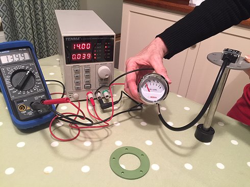
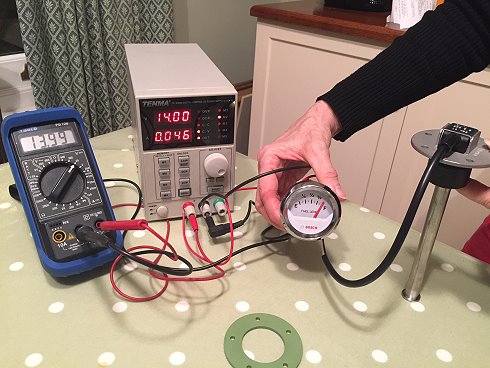
The left hand picture below shows the float somewhere between full and empty, near 1/2 full.
The right hand picture below shows the wiring diagram detailing how the test was done.
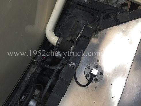
The two pictures below show the new reed type fuel sender fitted to the tank.
More technical information on the reed type fuel senders -
The reed type fuel gauge comes in several formats -
US system 240-33 ohms (that means 240 ohms tank empty and 33 ohms tank full) and the European system
0-90 ohms (and the less popular 0-180 ohms). The flange options are either SAE 5 hole (US) or screw
in European 1.25" BSP thread.
The gauge must be the same type otherwise with a 0-90 gauge on a 240-33 sender the pointer would go backwards.
(If you have an original GM Advanced Design sender and gauge cluster it will be 0-30 ohms and the only
option will be an original sender, not a reed sender.)
For more modern gauge types the advantages of reed sender are -
Compact so float not likely to get snagged.
Sensors are not in the fuel, they are encased in the aluminium tube.
Usually better build quality.
Pointer much less likely to have rapid fluctuations while driving.
Less moving parts should make them more reliable. Only the magnetic float moves. reed sensors are magnetically
operated switches inside the barrel. No bearings, no slider on a track. No moving parts except for the float.
Disadvantages are -
You have to buy the correct length. No adjustment. Dip the tank with a ruler.
The float does not go right to the bottom of the tank and so when the gauge reads empty there is still a couple
of litres of fuel in the tank. I see that as an advantage.
Tends to be more expensive (although you can buy higher quality variable resistor float types at a similar price)
Test equipment used -
Bench power supply set to 14v to simulate alternator output voltage when engine is running.
Multimeter.
Reed sender $55 (�40.00)
Spare Bosch fuel gauge $16.00
Also note high quality neoprene gasket $5 Note - Float is extremely light. Feels like plastic. Must be hollow.
Suppliers -
As already stated on this page, the fuel gauge comes from Summit Racing.
The reed type fuel sender and neoprene gasket came from WEMA.
modern electrical gauges but still look original.
Modifying the 4 gauges so that modern electrical sensors can be used and a safer voltmeter for battery
charge monitoring (without affecting appearance / still looks original).
The problem with the gauges is they use 1947-53 technology and this has many disadvantages.
1. The oil pressure gauge.
A narrow pipe goes from the engine to the gauge and the pipe contains oil at high pressure. The correct name
for the gauge (in Physics) is a Bourdon Gauge. This is a flat pipe in a curved shape. When the oil pressure
increases (e.g. truck is started) the curved flat pipe tries to straighten out. A blow type "party trick" is
actually a paper Bourdon Gauge. When blown into it straightens out (due to increased pressure) and makes a noise.
The problem with this type of gauge is the issue of the pipe leaking usually at a joint and oil leaking into the
cab and onto the carpet at high pressure. This also makes the vehicle unusable as oil from the engine is being
lost and oil pressure is falling. Leaks at the junctions is usually due to a failed "olive" (ferrule). Modern
gauges are electrical using an electrical sensor in the engine and wires to a moving coil (or digital) meter.
2. The battery charge indicator gauge.
This is an ammeter. The current from the battery to the fuse box (which carries all of the current except the
current going to the starter) must go through the ammeter. This means the wires going to and from the ammeter
are carrying a massive current of over 30A. Any kind of short circuit and the wires will burn and melt. Using
an ammeter for monitoring battery charging is a fire risk. The modern method is to monitor the charging and
discharging voltage not the current. Only a very small current goes through a voltmeter. A voltmeter is a
moving coil, moving magnet (or digital) meter.
3. The fuel gauge.
The original 1952 meter is a moving magnet meter. A magnet is connected to a pointer and held between two coils,
the sender unit in the fuel tank consists of a float connected to a variable resistor, the variable resistor is
connected across one of the coils on the fuel tank gauge. The sender unit must have the correct value of
resistance to suit the fuel gauge. The original moving magnet meter needs a sender unit with a variable resistance
of 0 - 30 ohms. When the tank is empty the resistor reads 0 ohms and when it is full the resistors reads 30 ohms.
A modern fuel gauge uses a moving coil meter. (The coil is within a magnetic field). Here a typical sender unit
has a variable resistors with a value of 240 ohms when the tank is empty and 33 ohms when the tank is full.
The water / oil temperature gauge.
The original mechanical temperature gauge used an inflexible thin copper capillary between the engine and the gauge.
This is also a Bordon Gauge. The coolant heats up the alcohol in the gauge and it unwinds moving the pointer. A modern
gauge is a moving coil (or digital) meter. The sensor is a modern electrical sensor and the sensor is connected
to the gauge by wires. The gauge is sensing changes in voltage and is calibrated in degrees.
From all of this background information it is clear that modern gauges can all be moving coil or moving magnet meters
with electrical wires connecting to the engine sensors, fuel tank sender or to the battery. All of the currents going
through the meters are low as the meters are actually voltmeters but calibrated to the 4 types of monitoring
parameter required.
Moving magnet meters. What to buy.
Modern moving magnet meters are quite cheap. Typically they are about $20 each (x4) and about $15 for a matching
tank sender unit. The other gauges come with the appropriate sensor where applicable. This means all 4 of the
gauges and sensors are less than $100. They are - Bosch Performance (formerly Sunpro) gauges 8201, 8202, 8205
and 8209 and are all available from Summit Racing. The problem is - They are all separate and do not look
original like the original cluster which holds the 4 original gauges. It is possible to buy a cluster of 4
moving coil meters and the cluster exactly fits the hole in the truck, however, all of these after-market
clusters for the truck look after-market. None of them look like the original cluster. Clearly this is a
matter of opinion but I don't think anything looks as good as the original cluster. The whole point of this
project is to make a cluster which looks original but uses modern metering.
The ideal fuel sender unit for this type of fuel gauge is detailed towards the bottom on this page.
Aims.
The purpose of this project is to see if the 4 separate moving magnet meter gauges can be stripped out of their
enclosures and fitted into the original cluster. They will also need to look original with brown displays and
white/cream calibrations. A good start is that all 4 gauges listed above have a scale which has a small
curvature and of a similar curvature and length of curvature as the original gauges.
Converting the cluster.
Note a useful starting point - The voltmeter for measuring battery charge status. "Swapping your ammeter for a voltmeter"
There is some very good useful information by "Mike" at www.stovebolt.com modifications
We are not doing it exactly the same way and we are converting 4 gauges not 1, but it is very worthwhile reading Mike's notes.
All of the gauges needed cutting open using a mini grinder and 1mm cutting disk. Safety equipment must be worn.
Before cutting open the gauges, please read the update below for a better procedure for cutting the gauges.
At this point it is important to note that the gauges need to be checked. To check the gauges apply a voltage. Use
a bench power supply or a 12 volt battery. I used a 0-30v variable bench power supply. These are available for about
�40.00 ($60.00). I set it on 12V and 14V. e.g. the fuel gauge reads 3/4 on 12v and full on 14v.
There are 2 reasons why the gauges might not work-
1. There could be raggy edges on the metal (swarf) needing to be removed. Check the pointers move freely by moving
them with a finger. Remove the circular white calibrated display plate by carefully removing the two small bolts.
Cut raggy edges off near the bottom end of the pointer if required with a modelling knife.
2. It is likely iron filings will have got onto the magnets from the cutting disc. In our gauges, three of them did
not work properly. Removing the iron filings needs either good eyesight or a magnifying glass, a thin screwdriver
with a piece of thin double sided adhesive tape on the end forming a narrow tongue and about 1 hour (at least) of
painstaking removal. The reason for double sided tape is not because it needs to be double sided. This type of
tape has a rigid backing and so the tongue is not too floppy and can be applied to the filings on the magnets.
Keep changing the tape as more and more filings are removed. Especially also at the bottom of the magnet where
there is a narrow gap to slide the tape into. (Note- the magnets are inside the coils)
After cleaning / removing the filings, one gauges did not work perfectly. See update below.
The gauges were test fitted onto thin ply wood to test the spacing.
Laying the original gauge glass face on top of the gauge cluster checks the spacing.
A piece of stainless steel plate was sourced from a local fabrication company. They also cut it to the required diameter.
It has a protective film on the back. This was not removed. It is ideal for marking out using a pen or pencil and even
when finished it does not need to be removed.
The gauges were mounted onto the stainless steel circular plate.
Laying the gauge face on top of the gauge cluster checks the spacing.
Making the new (original appearance) decals.
Once again my compliments to Mike at www.stovebolt.com for his advice on this subject. I used a different method
but was able to use one of his templates to help me. The program I am most familiar with and have used for many
years is Serif Page Plus (version X7 at the moment). This is a very inexpensive program and works extremely well.
I used it to produce the new lettering. I downloaded the voltmeter jpeg from the �stovebolt page� and inserted it
into Serif. This gave me two very important starting points. Since the import was actual size, it gave me the size
of the lettering. Secondly it gave me a guide to match the background colour and the colour of the lettering. I
decided I preferred the light cream lettering to the off white lettering. I could not find a font which was exactly
the same but I did find a font which was close. Using the decal from Mikes page I inserted new lettering.
It is important to make 2 decals before using Serif, Simply invert the decal and save it to a new file as two
of the decals need to be the other way round for the oil pressure and the water temperature. Within the Serif
program it is possible to set the background colour and the letter colour. I found the best match for the
background was Red 42, Green 34 and Blue 18. The best match for the light cream lettering was - Red 255,
green 245 and blue 215. The font I used for the numbers was - "BoltsSF" and for the letters (E and F)
for the fuel gauge - "Franklin Gothic Medium Cond" The large lettering size was 50 and the small lettering
size was 20. The width was set at 50% for the most of the letters and 70% for the "1/2" on the fuel gauge.
All of this information may be useful for anyone using a different program but you can download the actual
Serif files below if you intend to use that program. This would be the easiest option as the work has been
done for you. However, it only took me about 3 hours to do this work and anyone good at IT and used to this
type of process could use a different program. I purchased Serif Page Plus X7 from Amazon for �30.00 ($42.00)
I recently also used it to draw the plans for the extension on my daughters house and countless other uses. If
you not familiar with this program, it does not matter as all you have to do is download the 4 files below,
open them in the program and print them. They will automatically print the correct size. jpgs are also
available below but they might not print the correct size and may need adjusting.
The "Serif" file - All Decals. The jpg file - All Decals
The circular white calibration plates were put onto the new (old style) decals and using a small drill just
held in the fingers, the holes through the card were drilled. The decals were then mounted onto the gauges
using the small bolts. Tighten very carefully by feeling for when the bolt is fully in but not compressing
the card. It is possible (according to Mike) to strip the threads but this did not happen here.
A tin of white and a tin of cream �Humbrol� modelling paint and a thin brush was purchased from a local modelling
shop. About 6 parts white to one part cream was used and the red pointers were painted. The red still showed
through and a second coat was needed.
The original gauge back was cut. The pictures show the rough cut and then below the cleaned up cuts and some
paint applied. A mini grinder with 1mm cutting disc did most of the work. The cutting disc was later replaced
with a grinding disc to finish off. A smaller diameter worn grinding disc worked best. During this process one
of the lugs which holds the gauge on the inside of the dash dropped off. Our local fabrication shop welded it
back on with a small torch, gas welding appliance. I am very lucky ... my business buys many items every month
from them and so "truck jobs" are free!
It is important to get the spacing right between the new back plate and the old one so that the glass face sits
on the top correctly. I found one nut, four thin washers and one thick washer provided the 8mm which worked well.
Since photocopying thick gauge paper (card) was used. The decals had enough rigidity to be self supporting.
The paper (card) was from one of the "Jessop" stores. Printing using a normal budget printer worked fine.
A plastic ice cream carton top provided the insulation on the back. This will be held in place by the illumination bulb holders.
It is now possible to see how close this modern set of gauges looks compared to an original cluster from 1947-53
In my opinion it looks much better than the after-market modern gauges now available which look nothing like an
original gauge. Time? I started a couple of weeks before a 4 week business trip and finished a couple of weeks
after I got back. If I had to add all of the hours together, it would probably have been about a weeks work.
However, now that you can see how it is done (I had to design and solve problems) it should take less than that.
Update 31st May 2016 - Illumination problems.
Putting bulbs into the 4 holders in the backs of the 4 gauges produces poor results with both hotspots and
an uneven spread of light. A test with a bulb right in the centre produced perfect results. The gauge cluster
now needs a strip down so that a hole can be made in the centre for one bulb. See the next update below.
Update 31st May 2017 - Illumination problems solved.
Check out the picture above of the back of the gauge which also shows the wiring connections. There are 5 places a
pea bulb can be pushed in, it can go in each of the meters, or you can see I put an extra one in the centre.
If you put bulbs into the 4 meter holes the light is too bright and not diffused enough. It is best to fit a
socket right in the centre. Epoxy Resin was used to fit this extra socket. Looking at the plastic back cover
above, an extra hole is needed in the centre for the single pea bulb. When this was tested it was the opposite
problem, not quite enough light to spread through the whole cluster. The solution (update February 2018) was
to coat some surfaces inside the gauge with aluminium foil / kitchen roll. It was stuck on with the same spray glue
used to stick the fabric and foam to make the door panels. It was stuck around the inside perimeter of the whole
4 gauge cluster casing, under the pea bulb, on the inside of the glass front in the centre and on the edges of
the individual gauge casings which border the pea bulb. All of this reflective foil then allowed the pea bulb
to provide the ideal amount of diffused light for the whole cluster. Pea bulbs did come with the meters but they
are filament and white. After a bit of research, 12V blue LED SG9 bayonet fitting pea bulbs were found at
www.rapidelectronics.co.uk at �1.19 each (they are also available from Amazon). The extra push-in pea bulb
fittings (with cables cut off and no bulbs inside them), can be pushed into the other holes as this all
helps to hold the plastic cover (which forms an insulated back) onto the back of the gauge cluster
Update March 2017 You can see in the pictures below, there are extra gauges hanging below the dash.
The chrome surrounds which come with the Bosch gauges are ideal for hanging extra gauges. Using a custom made
bracket across the top of the column there are 2 extra gauges, symmetrically placed each side of the column
under that dash. The one on the left is a rev counter and the one on the right monitors the oil pressure in
the automatic transmission. This needs a 0-400psi gauge made by "VDO" A VDO 0-400psi sender has to be
screwed into the side of the transmission and wired to the gauge Unfortunately VDO (the only company
who makes these meters) do not do a meter which looks as good as the meter on the left (would have
been better if they had matched) but anyway the 2 meters still look fine.
Update August 2017 How to avoid iron filings from getting into the meter movements.
Following the procedure above to cut open the gauges, there is a danger that iron filings will get
into the meter movements. Whilst it is possible to remove these using the method listed above,
this may not be 100% successful. With this cluster there was a problem with the fuel gauge reading
low even though the attempts to remove all filings seemed to work. It had to be replaced and so
a better method was found to cut the casing with the movement already removed.
The solution was to remove the internal meter movements before cutting the casings with a mini grinder
and cutting disc. This can be done by prising the front of the gauge off with some pliers. Round
nose pliers worked well. Removing nuts on the back and the internal movement can be slid
forward and completely removed. The casing can then be cut. Clean up and refit the
movement. See pictures above of the casing with front prised off.
Update March 2017. Fuel tank gauge accuracy upgrade.
The bed was removed from the truck so that some update work could be done to the fuel tank and fuel sender unit.
(See the original notes, designs and building of the fuel tank in 2008)
Tank system mods -
This mainly related to installing a more accurate fuel gauge sender unit, however, some extra
work was done on the filler tube and the venting pipes. It is very important all venting pipes
are terminated into the filler tube so that if any fuel comes out of them it can't spill. Secondly
there was an obstruction in the filler pipe designed to insure the correct fuel nozzle went in but
this was causing problems. Removing it enables the fill rate (flow rate) to increase.
Fuel sender unit -
The fuel senders in most fuel tanks are pretty crude. They involve a float and variable resistor
inside the fuel. A better system uses reed switches and the detection system is not in the fuel.
The picture above right shows the old variable resistor type sender removed and a steel ruler dipping the
tank for depth. The reed type senders come in various lengths and the depth of the tank needs to be known.
The two pictures below show the reed sender unit. The float is in two positions. The reed sensors which do
the sensing are inside the sealed aluminium tube and not in the fuel. This makes for improved reliability.
The 2 pictures below show resistance measurements being taken. Float high reads 0.156 ohms (almost zero).
Float low (empty fuel tank) reads 241 ohms. This is exactly correct for the type of Bosch fuel gauge being used.
The next two pictures below show the float low and high for an empty and full fuel tank. The power supply and
multimeter show 14 volts which is correct if the truck was driving as the alternator produces about 14V.
The left hand picture below shows the float somewhere between full and empty, near 1/2 full.
The right hand picture below shows the wiring diagram detailing how the test was done.
The two pictures below show the new reed type fuel sender fitted to the tank.
More technical information on the reed type fuel senders -
The reed type fuel gauge comes in several formats -
US system 240-33 ohms (that means 240 ohms tank empty and 33 ohms tank full) and the European system
0-90 ohms (and the less popular 0-180 ohms). The flange options are either SAE 5 hole (US) or screw
in European 1.25" BSP thread.
The gauge must be the same type otherwise with a 0-90 gauge on a 240-33 sender the pointer would go backwards.
(If you have an original GM Advanced Design sender and gauge cluster it will be 0-30 ohms and the only
option will be an original sender, not a reed sender.)
For more modern gauge types the advantages of reed sender are -
Compact so float not likely to get snagged.
Sensors are not in the fuel, they are encased in the aluminium tube.
Usually better build quality.
Pointer much less likely to have rapid fluctuations while driving.
Less moving parts should make them more reliable. Only the magnetic float moves. reed sensors are magnetically
operated switches inside the barrel. No bearings, no slider on a track. No moving parts except for the float.
Disadvantages are -
You have to buy the correct length. No adjustment. Dip the tank with a ruler.
The float does not go right to the bottom of the tank and so when the gauge reads empty there is still a couple
of litres of fuel in the tank. I see that as an advantage.
Tends to be more expensive (although you can buy higher quality variable resistor float types at a similar price)
Test equipment used -
Bench power supply set to 14v to simulate alternator output voltage when engine is running.
Multimeter.
Reed sender $55 (�40.00)
Spare Bosch fuel gauge $16.00
Also note high quality neoprene gasket $5 Note - Float is extremely light. Feels like plastic. Must be hollow.
Suppliers -
As already stated on this page, the fuel gauge comes from Summit Racing.
The reed type fuel sender and neoprene gasket came from WEMA.
Click on the banner below to see our new web site.
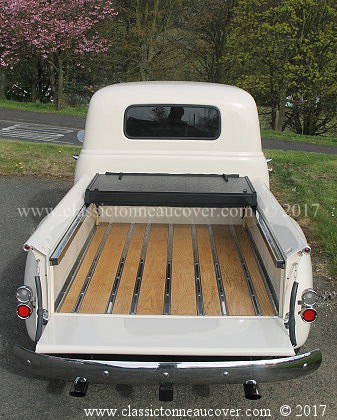
It is about a new hard tonneau cover (bed lid) for the 1947-53 Chevy truck.
Model - "Zero Impact Ultimate 3100" Tonneau cover. Fit without drill holes in your truck.
You can read about it and you can order it. It is available now.

Click on the banner above.
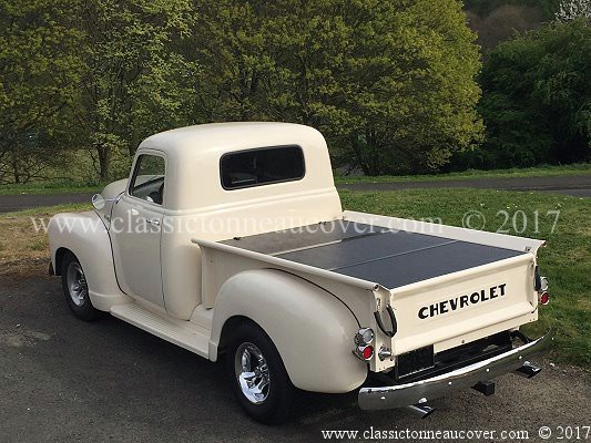
� A hard tonneau cover. Completely rigid, solid and strong. Folding.
� Zero impact. It can be fitted without drilling any holes in the truck. All paint work protected.
� Does not detract from the appearance of the truck. Enhances the appearance of the truck.
� With the cover removed and just the hardware kit showing it still looks "show quality".
� When the cover is fitted but open it still looks excellent and does not detract in any way from the appearance of the truck.
� The cover can be removed in under five minutes.
� All materials and finishes are of the highest quality.
� There is a choice of hardware support finishes to suit painted or patina trucks.
� A water drainage system is included to prevent water from leaking into the bed.
� Better than original factory quality. Just look at the pictures above.
� The model shown is supported by a mirror polished stainless steel installation kit.
� This tonneau cover is for the - 1947, 1948, 1949, 1950, 1951, 1952, 1953 Chevy truck. Advanced design stepside 3100.
It is about a new hard tonneau cover (bed lid) for the 1947-53 Chevy truck.
Model - "Zero Impact Ultimate 3100" Tonneau cover. Fit without drill holes in your truck.
You can read about it and you can order it. It is available now.
Click on the banner above.
� A hard tonneau cover. Completely rigid, solid and strong. Folding.
� Zero impact. It can be fitted without drilling any holes in the truck. All paint work protected.
� Does not detract from the appearance of the truck. Enhances the appearance of the truck.
� With the cover removed and just the hardware kit showing it still looks "show quality".
� When the cover is fitted but open it still looks excellent and does not detract in any way from the appearance of the truck.
� The cover can be removed in under five minutes.
� All materials and finishes are of the highest quality.
� There is a choice of hardware support finishes to suit painted or patina trucks.
� A water drainage system is included to prevent water from leaking into the bed.
� Better than original factory quality. Just look at the pictures above.
� The model shown is supported by a mirror polished stainless steel installation kit.
� This tonneau cover is for the - 1947, 1948, 1949, 1950, 1951, 1952, 1953 Chevy truck. Advanced design stepside 3100.
Link to our own museum site
Rewind Museum. A Museum of vintage consumer electronics.
See
www.rewindmuseum.com/vintagesatellite.htm
For old Satellite receivers with knobs on!
(and other historic items) - and
Vintage reel to reel video recorders. Vintage VHS
and Betamax VCRs. Vintage video cameras. Vintage
Laser Disc. Vintage Computers. Old telephones,
Old brick mobile phones. Vintage Hi Fi, Old reel
to reel audio and early audio cassette decks.
Including, the history time line of vintage
consumer electronics ... and much more .....
So see,
www.rewindmuseum.com/home.htm

It is well worth a visit.
Only The Satellite Superstore brings you
great products, advice and it's own museum

Rewind Museum. A Museum of vintage consumer electronics.
See
www.rewindmuseum.com/vintagesatellite.htm
For old Satellite receivers with knobs on!
(and other historic items) - and
Vintage reel to reel video recorders. Vintage VHS
and Betamax VCRs. Vintage video cameras. Vintage
Laser Disc. Vintage Computers. Old telephones,
Old brick mobile phones. Vintage Hi Fi, Old reel
to reel audio and early audio cassette decks.
Including, the history time line of vintage
consumer electronics ... and much more .....
So see,
www.rewindmuseum.com/home.htm
It is well worth a visit.
Only The Satellite Superstore brings you
great products, advice and it's own museum
A Useful Search Engine.

Google.
An excellent very comprehensive search engine. Find everything.
Probably the biggest search engine in the world.
www.google.com
Google.
An excellent very comprehensive search engine. Find everything.
Probably the biggest search engine in the world.
www.google.com
Link to our main site. Satellite TV.
Sponsored by Vision International.
Note. One of our businesses, Vision International (established 1991) sponsors the
1952 Chevy truck site including financial support for this web site.
Vision International is one of a group of businesses that we have in the field of
Satellite TV. This is a link to our sponsor.
Tune in an extra 10,000 channels? No you don't need a large dish but we do sell
big dishes as well. Watch the world? Links to some of the pages are below,
Satellite dishes Transparent Dishes Motorised dishes LNBs Satellite Receivers
Mobile / caravan satellite Multiswitches Satellite finder meters All satellite products.
This 1952 Chevy truck web site is maintained on a non-profit
making voluntary basis. Our main business website is at
www.satellitesuperstore.com/cat.htm
Our main business is satellite TV and we are a specialist
satellite company. We supply satellite goods in the UK
and worldwide including fixed and motorised satellite
systems, accessories, and installation equipment.
Web site copyright © 2021 Vision International. All rights reserved.
For all questions & comments about this site's content, contact - Dave
using our email address - (We only accept questions in English.)
For all questions & comments about this site's content, contact - Dave
using our email address - (We only accept questions in English.)